
Inputs and outputs
Getting started with the BBC micro:bit - Lesson 2
Objectives
- To create simple programs to control the LED matrix on the micro:bit
- To understand inputs and outputs on a computer
- To program the micro:bit’s LED matrix to respond to different inputs
Lesson Resources
- Lesson Slides
- micro:bits and USB cables (approximately 1 between 2 students)
Lesson 1 - Getting started and the LED Grid
Lesson 2 - Inputs and outputs
Lesson 3 - More inputs and outputs
Lesson 4 - ‘Beat the buzzer’ – Pin inputs and outputs
Lesson 5 - Using conditions and random numbers
Lesson 6 - Variables: Building a scorekeeper
Introduction
Recap the last lesson and what they learned about the micro:bit in the last lesson.
- What is a micro:bit?
- What did we program it to do in the last lesson?
- Can you program three different images to show in sequence on your micro:bit independently? (or with a partner)
Inputs and Outputs
In the last lesson we briefly discussed some of the micro:bit’s features, including the A and B buttons and the accelerometer. We will be making use of some of these features in this lesson.
Ask - What are inputs and outputs?
Inputs are a computer receiving data, data going IN, e.g. from buttons, sensors etc. Outputs are a computer sending out data, information going out to make things happen, e.g. lights, sounds, movement.
Take a look at this page and video on BBC Bitesize for more about inputs and outputs.
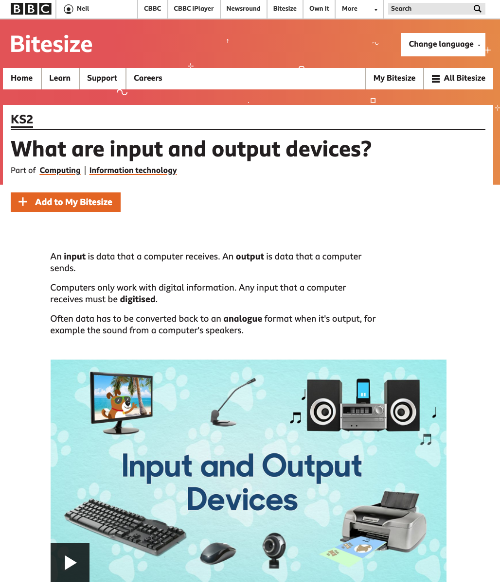
Source: https://www.bbc.co.uk/bitesize/topics/zf2f9j6/articles/zx8hpv4
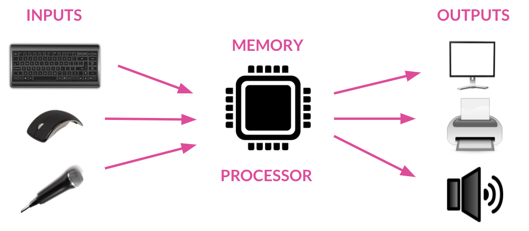
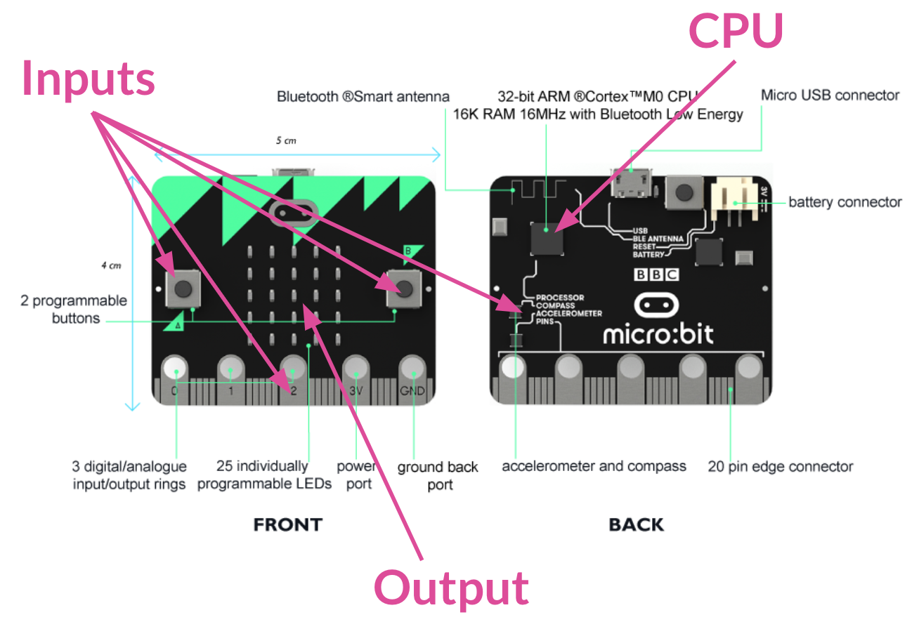
All computers have four main components. Inputs and outputs are key but they mean and do nothing without the computer’s CPU (central processing unit), which makes sense of inputs and tells outputs what to do in response to an input. Can you find the processor on your micro:bit?
The micro:bit has a number of possible inputs and we’re going to be investigating them in this lesson to make different things happen (outputs).
Let’s start with the buttons on the front of the micro:bit. Take a look at this video from Microsoft Makecode to find out a bit more about how buttons work and how they can be used as input triggers.
As the video shows, ask the students to try out getting their A and B buttons to display different images on their LEDs.
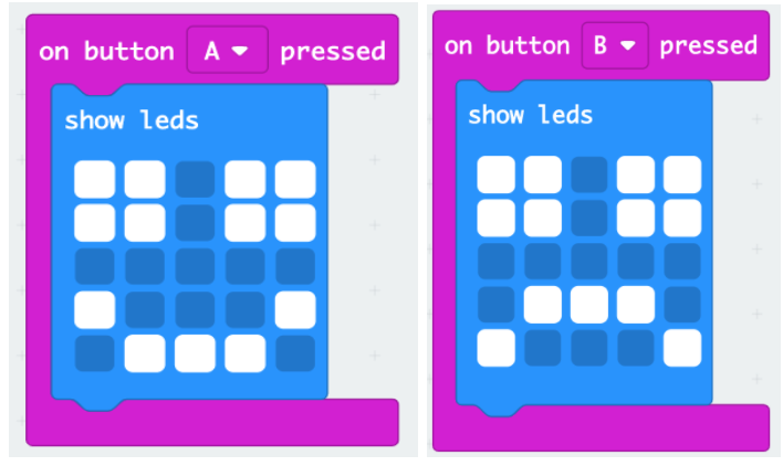
Then ask the class, how else could I get a third image to show on the LEDs by still using just the buttons?
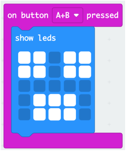
The micro:bit has an option that says when the A and B buttons are pressed together, let’s try that too. Make a third, different image for this one:
Challenge time
But the micro:bit has other inputs beyond the buttons, most of which are linked to its movement sensors (the accelerometer and compass). Set the class the challenge: how many other inputs can you find on the micro:bit? Program it so a different image (output) is shown with each input you use.
Give them time to investigate this with their partner, noting down what they find as they go.
These are the main inputs they should be aiming to find (all in the input category of blocks).
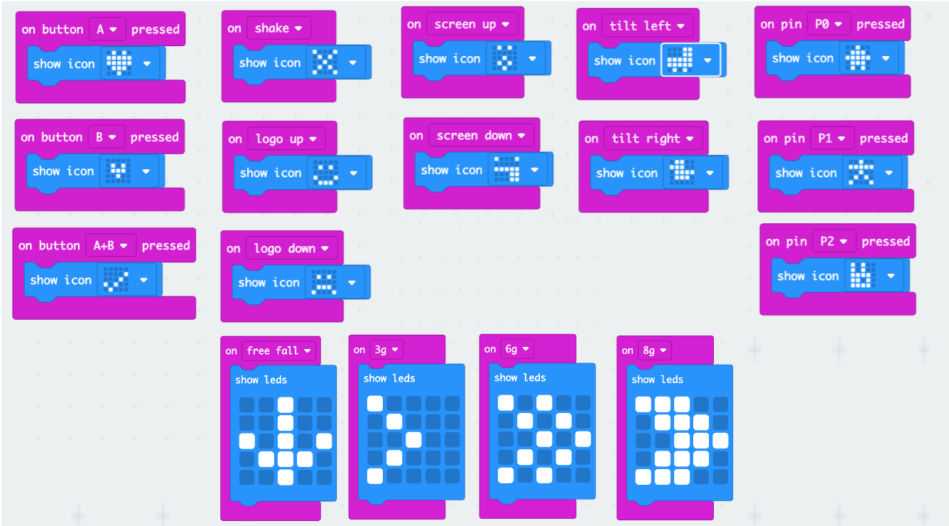
‘Logo up’ and ‘Logo down’ refer to the micro:bit logo on the back and indicates whether it’s facing up or down vertically. ‘Screen up’ and ‘screen down’ refers to if the micro:bit is facing up or down horizontally.
The ‘On pin pressed’ blocks refer to the gold 0, 1 and 2 input pins at the bottom of the micro:bit. To activate these you can create a circuit with your body from any of the pins (pinch the front and back of the pin with your thumb and forefinger on your left hand) to the GND (ground) pin (pinch the front and back of the GND pin with your thumb and forefinger on your right hand). A small (and safe) current will pass from the pin, through your body and into the ground pin, completing the circuit and triggering the input. We'll use these in another way in future lessons.
The other input blocks not shown above also work but are trickier to demonstrate.
‘On free fall’ is exactly what it sounds like, the micro:bit can detect when it is falling. However this is hard to do when it’s plugged into your computer with a short USB lead and if you also have some of the directional inputs activated (‘on shake’, ‘screen up’ ‘logo up’ etc), they can interfere as it’s likely one of those conditions will also be being met. The best way to get it working is use a much longer USB lead or the battery pack to allow the micro:bit to be dropped (catch it safely!) and delete other input blocks.
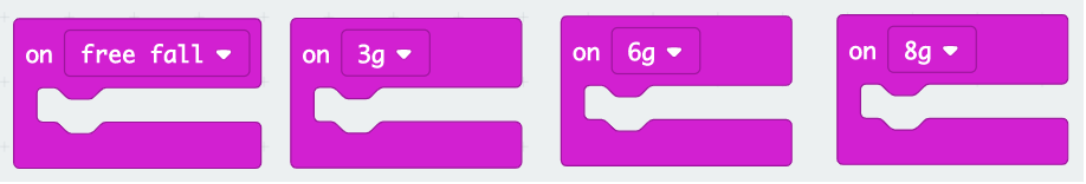
The 3, 6 and 8g blocks refer to the gravitational force that is acting on the micro:bit (and therefore measure its acceleration). 1g is equal to the force of gravity at the Earth's surface (which is 9.8 meters per second per second). Again, these are harder to demonstrate for the same reasons as described above, but can be triggered by moving the micro:bit through the air at different speeds (you need to be fast to trigger 8g!). A long lead, battery pack and no other inputs are again needed for this to work well.
It's worth noting that when you have a lot of these inputs programmed at the same time, some can interfere with each other. For example, if you have 'free fall' and 'screen up' both programmed, when you drop the micro:bit the screen could feasibly be facing upwards (so you can see the LEDs), so both inputs would be triggered, so which one would take precedence and which image would be displayed?
Others won't interfere with each other at all, but bear in mind that to get some to work well you may have to delete others.
Plenary
- What inputs did you find on the micro:bit?
- Take a look at the back of the micro:bit, do you think it has any other features that could be used as inputs?
- What outputs does the micro:bit have?
It has lots of different ways to trigger outputs. Of course the outputs don’t have to just be images on the LED screen! In some of the later projects we’ll use inputs to make different outputs occur, and did you know that you can plug a micro:bit into your computer and use it as a control device for the latest versions of Kodu and Scratch?! Take a look at some of the cool Kodu features that work together in this video.
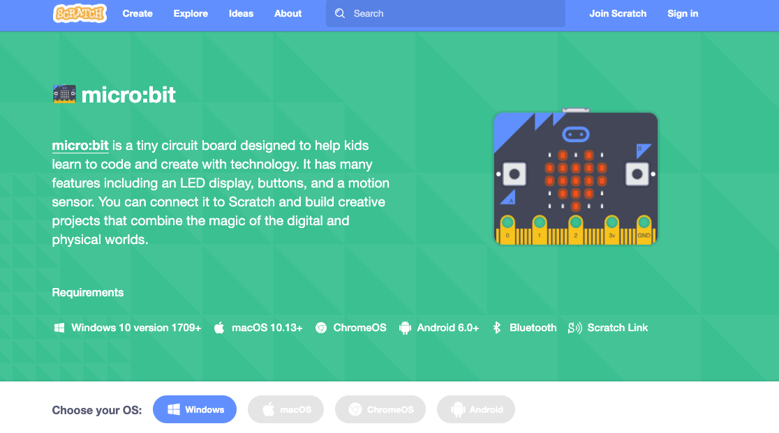
Find out more about using the micro:bit in your Scratch projects here
How do you think your micro:bit could be used to control a video game?